![]()
Picture a young Alf Lysholm peering into an 1878 book of German patent applications, looking for ideas. The company which had just appointed him Chief Engineer was in trouble. The former owners, Berger and Fred Ljungstrom had invested their companyÆs resources and personal fortunes in the development of a highly efficient steam turbine locomotive engine. They had developed a simple yet remarkably effective inlet air preheater for steam boilers, and the new turbine engine would blow the older piston designs away. Production of the steam turbine locomotives went into high gear in three locations. Yet, timing being what it can be, the ōnewer technologyö diesel and electric locomotives arrived on the market and stole the show. Back to the books!
LetÆs see, the Krigar compressor below right, patented in 1878 was a 2+2 helical lobe compressor ģquiet, efficient, compact, only made 1 Į psig, but it was quiet.
 |
Drawings above show the Krigar screw wheel compressor, (right) and the first Lysholm 3 lobe rotary screw design, (left). The Lysholm design offered a gradual compression of the entrapped air prior to exposure to the high pressure air at the discharge port. It was good for an oil free 2:1 compression ratio. While capable of higher pressure than competing designs shown below, it was still quiet. Now we were getting somewhere.
 |
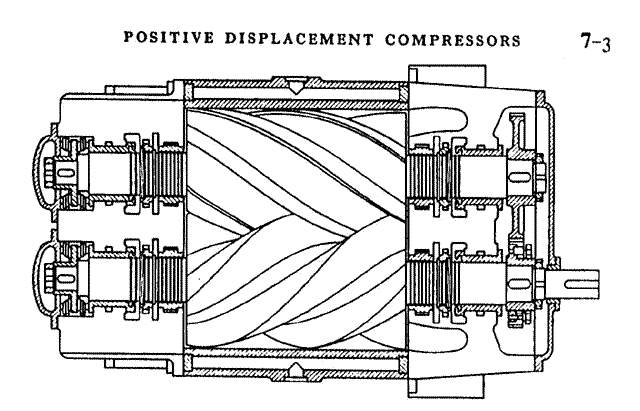
The sketch below is from a 1942 paper in which Lysholm refers to the ōold profileö. Some older Comp-Air distributors may recognize it from the Howden WK82 airends used in late 1970s Kellogg American KRS 15-30 packages, many of which are still running today.
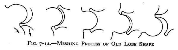 |
High production costs were associated with this profile as the rotors had to be more carefully machined and lapped due to the long contact area. (Our experience with the WK82 actually showed this older profile to be very durable).
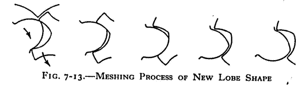 |
Life is full of compromise and rotor design is no exception. It is fairly easy to see more opportunity for leakage in the newer, easier to manufacture, asymmetrical design shown aboveģnewer in 1942.
 |
The above drawing is of a Lysholm-Holman single stage oil free compressor from around 1940. It delivered 4,700 cfm @ 45 psig at only 3,000 revolutions per minute. The sealing strips were left high and allowed to seat themselves in to the cylinder casings. According to Mr. Lysholm, this allowed them to achieve the ideal clearance of .001 inch per inch of rotor diameter. Although the rotors had timing gears on the drive end, Mr. Lysholm mentioned that the female rotor was driven primarily by aerodynamic forces, with only 2-3 % of the energy transmitted through the gear set.
To truly appreciate the achievements of this man and his staff, you have to realize that the rotors were cut with shapers, flycutters, end mills and files.
Among the numerous contributions Mr. A.J.R. Lysholm helped bring to his company and to our world are the hydraulic torque converter, turbine blade design and the rotary screw compressor. It pays to study!
By 1951 the hydraulic and turbine divisions had been spun off and the company changed its name to Svenska Rotor Maskiner AB, or SRM for short. A quick look at the current list of SRM licensees (following this article) will affirm the position they hold in rotor design.
We would like to thank retired MIT Professor and steam engine guru, Dr. George Nutz for sharing papers used in the writing of this article. We also tip our hats to the employees and management of SRM for their companyÆs unique contributions to our industry.
We do not wish to diminish the many clever minds and companies that have played a part in development of current rotary screw compressors. Most technologies grow from parallel paths, rather than along a straight line. Like the young Mr. Lysholm, we simply understand the value of an appreciation of the past.